CAD (Computer Aided Design) work has begun for the rebuilding of two Wb class Baldwin tank locomotives at the Rimutaka Incline Railway. Wb 292 and Wb 299 were salvaged from a dump site at Seddonville on the West Coast in 1989, having been dumped after withdrawal from service in 1958 and 1960. They have been in storage at Maymorn since 2008, and the frames of both locomotives are now inside the rail vehicle shed awaiting attention.
292 and 299 are two survivors of a class of twelve built in 1898 by Baldwin Locomotive Works, Philadelphia, U.S.A. They spent the greater part of their working lives based at Westport on the West Coast of the South Island, hauling coal trains from inland mines to the port. Two Wb class locomotives were originally based at Wellington, working trains to and from the Hutt Valley and Summit.
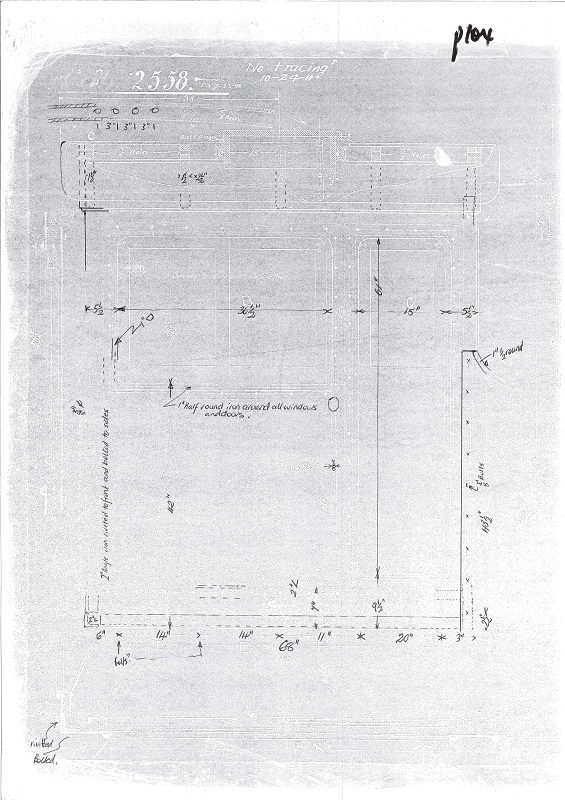
A reasonably full set of drawings exist for the Wb locomotives, including those originally shipped with the lcoomotives by Baldwin in 1898, plus a number of NZR drawings detailing changes that were made through their working lives. The more notable changes include fitting of new boilers in the 1920's - to an NZR design that was very similar to those fitted to Wf, Wg and Ww locomotives.
CAD brings the drawings together into an integrated, 3D model. Dimensions can be checked, parts try-fitted and errors / discrepancies identified early in the project, which will help reduce waste. Sub-assemblies can be put together to combine associated components. For example - frames, boiler, cab, tanks, trucks and other key parts of a locomotive can be compartmentalised and modelled separately. 3D views of sub-assemblies as well as the complete locomotive can be had - rotated, zoomed and inspected from diferent angles.
Over the past couple of months Trust members Ben Davidge and Hugh McCracken have been working through the drawings available - both Baldwin and NZR, along with inspection and measurement of actual parts from the Wb locomotives. The cab has been picked as a starting point sub-assembly - essentially a number of sheet and angle items that are relatively approachable for funding and fabrication, and can be made independent of much of the rest of the locomotive.
Following are a series of photos / plans that illustrate the progress made to date.
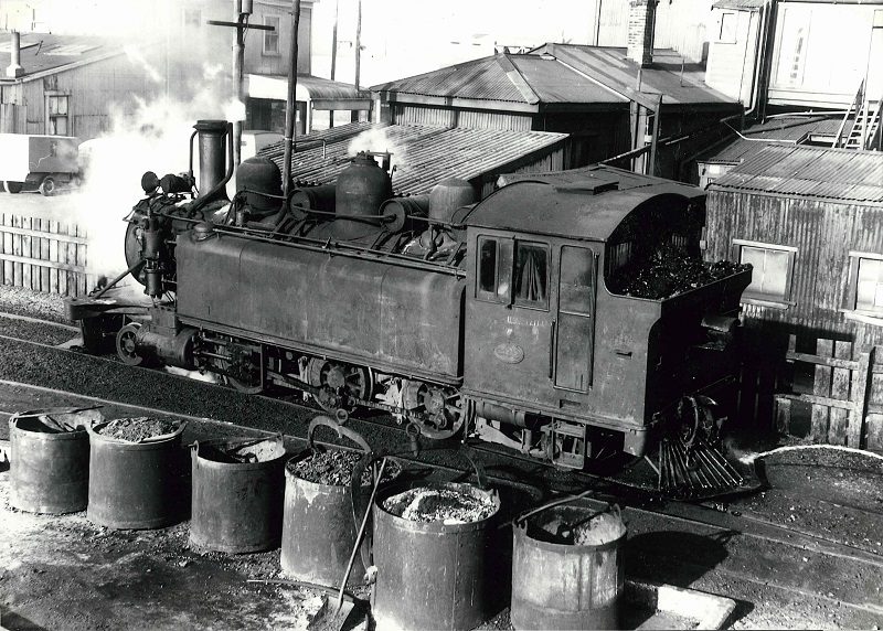
Wb 299 at Westport loco depot in November 1951, a similar perspective of the cab to that of the lead photo of this article. Photo: J Creber
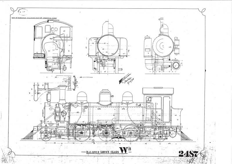
General arrangement drawing for the Baldwin Wb class locomotive - reference made to this for key details for the cab
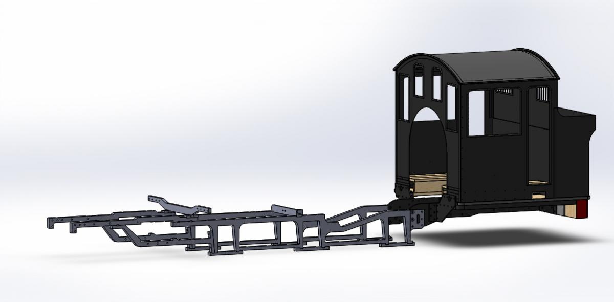
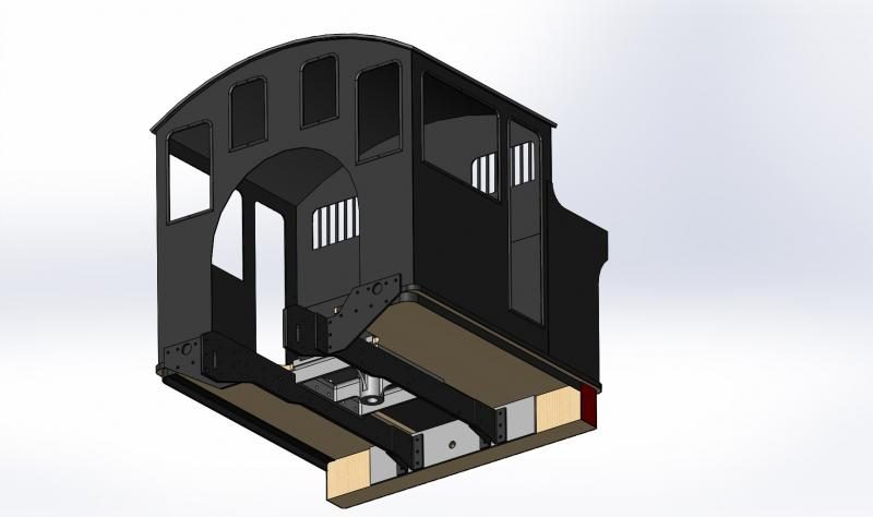
Cab, bunker, headstock and plate frame extensions modelled in CAD. Quite a few details to add in - including drilling pattern, sub-floor, handrails etc
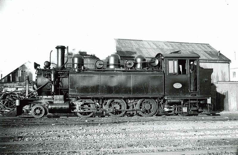
A similar side-on perspective of Wb 299 at Westport, taken by Hugh Bennett in May 1949 (neg 2339)
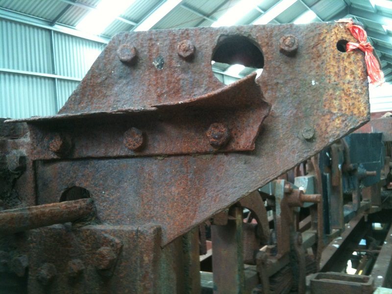
Tank and cab bearer of Wb 292 - an example of parts that will be referred to during CAD modelling. Remains of the cab sub-frame angle are still in place.
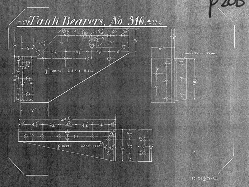
Baldwin drawing #316 - Tank bearers - details the component seen in previous photo.
Another view of the CAD model - underside of cab showing the plate frame extensions, sub-frame and cab board.
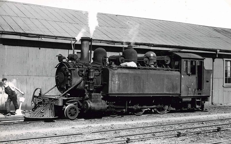
Another classic view of Wb 299 being shunted at Westport loco depot in November 1951, showing a front 3/4 view of the cab. Photo: J. Creber.
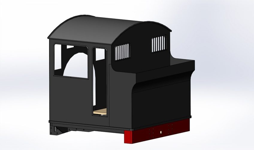
CAD model of cab and bunker, rear 3/4 view

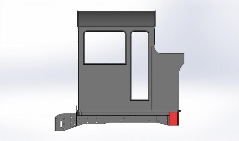
Side view of Wb 299 part-way through CAD modelling in April 2014.
Copies of cab drawings were quite difficult to read and interpret - CAD modelling has helped confirm that key measurements are correct