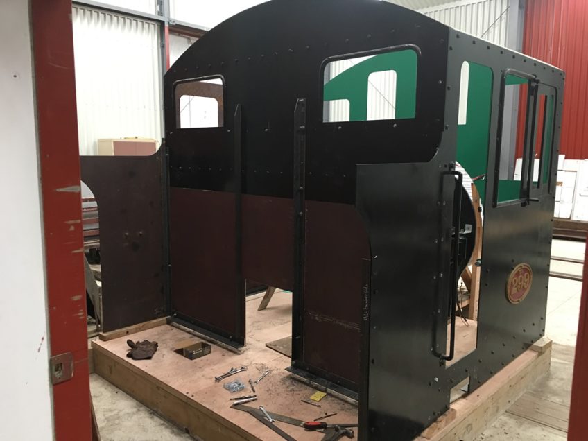
The cab and bunker of steam locomotive Wb 299 have received a lot of attention over the past couple of months. The bunker side sheet has been fitted on the fireman's side, complete with original footstep. The bunker front sheet has also been fitted, along with steel angle framework for the raised cab floor and bunker support. An original strengthening plate is in place below the rear cab windows, providing key reference points for bunker support angles.
The cab board is in place under the cab and bunker, comprising two sheets of 44 mm thick marine plywood, on a timber support frame. This provides a stable surface to locate, true up and fix the cab and bunker. The cab board will eventually be mounted on the locomotive, sitting on the main extension frames, rear headstock and steel angle subframe. These items are next on the list for attention.
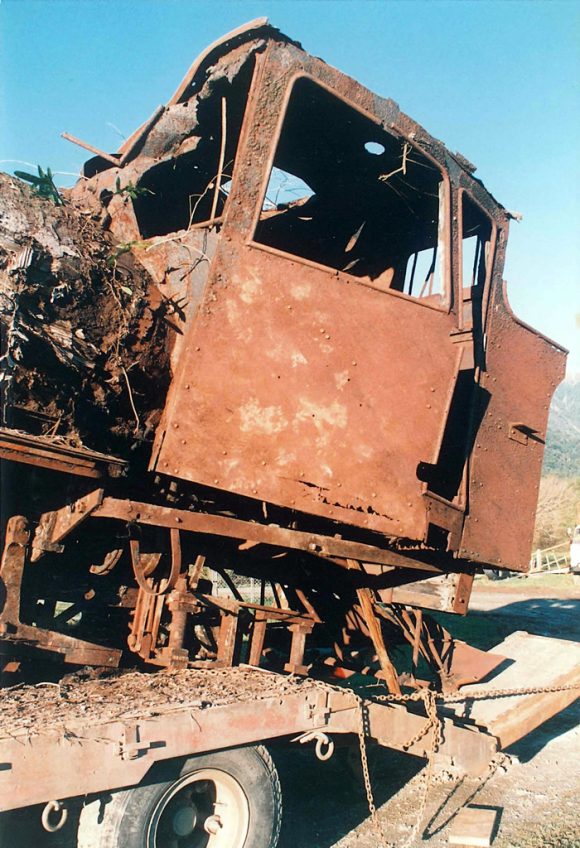
A glimpse back to 1989 when Wb 299 and classmate Wb 292 were recovered from Seddonville, West Coast. Interesting details of cab and bunker on fireman's side.
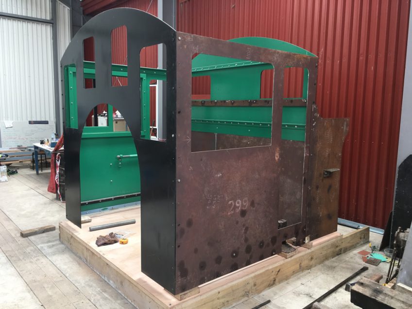
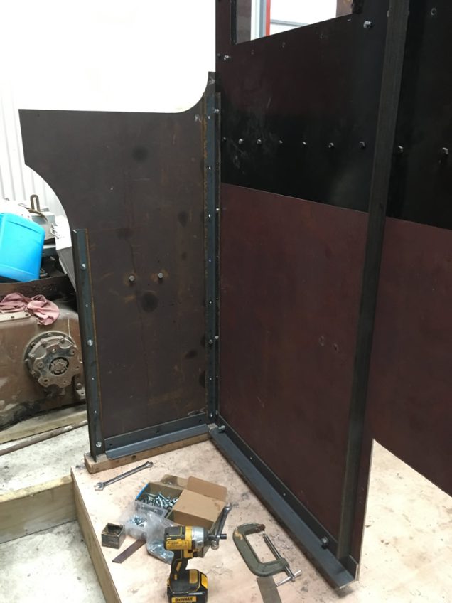
Fast-forward to 2019 with reconstruction of cab and bunker. A mix of new and original parts - e.g. original footstep fastened to new bunker side sheet.
Interior of cab, looking towards fireman's side, framing for raised cab floor fitted to side sheet.
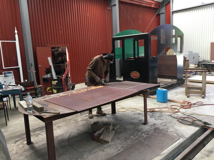
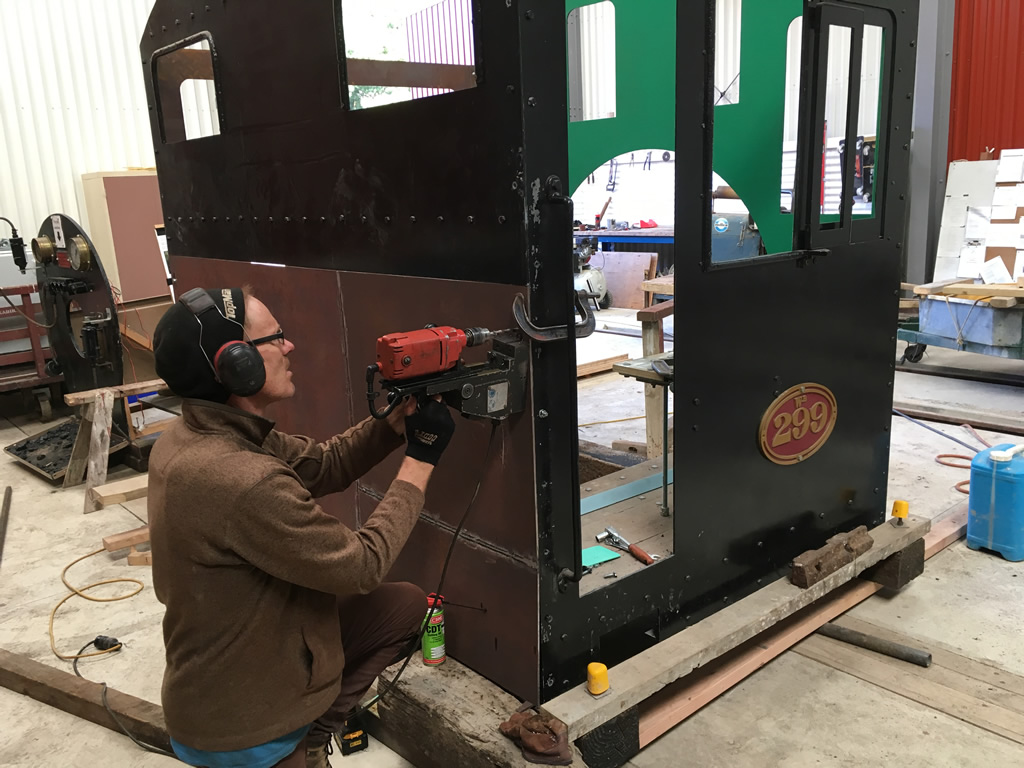
Hugh McCracken preparing bunker from spare steel sheet
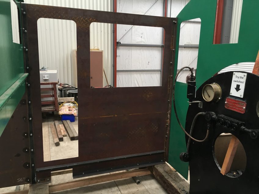
Cab board assembled under fireman's cab side, Wb 299
Bunker front and two sides fitted, coal hatch cut out and bracing angles either side fitted, tying cab back and bunker front together.
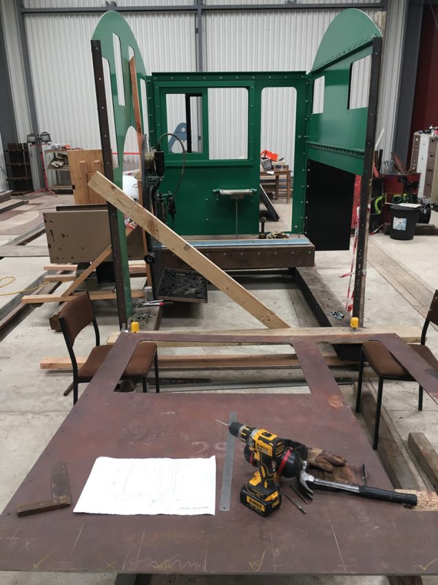
Fireman's cab side temporarily removed from the assembly to locate steel angles at base and to carry the raised cab floor.
Steel angle framework taking shape in the coal bunker. Heavier section angles are located at the base, owing to the weight of fuel carried. The coal chute has been cut out, seen to the right of the photo. Chute door and guides are next on the list of items to be fabricated and fitted.
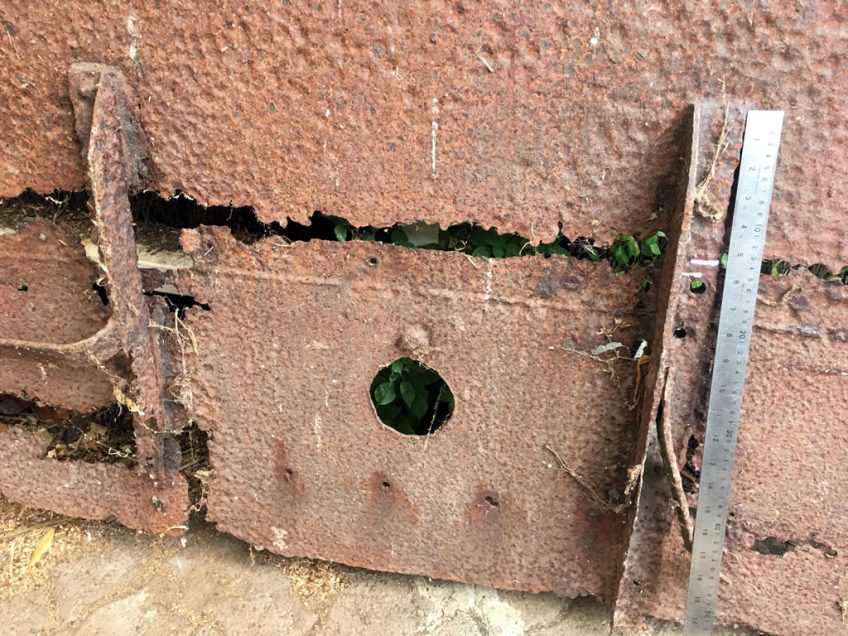
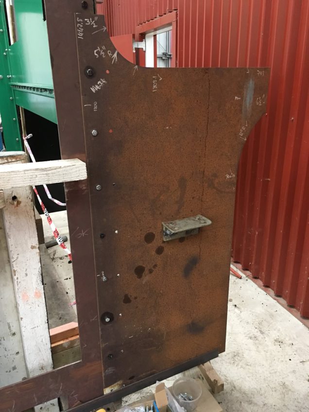
Checking measurements of a section of the original cab back. Details have been checked against original plans. Some alterations and additions were made "in service", for example the circular cut out, presumably made to provide a route for extracting and replacing boiler tubes or the regulator rod.
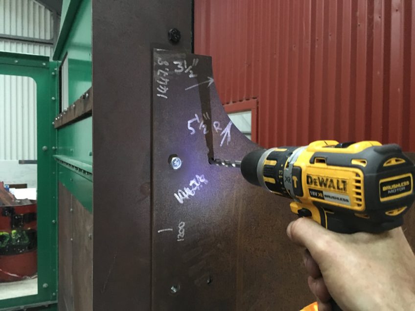
Details of the fireman's bunker side, showing measurement checks in white marker pen. The original bunker was extended in height circa 1917 by approximately 165 mm to provide additional capacity. Here we see pilot holes being drilled for the steel angle located between the cab back and bunker side.